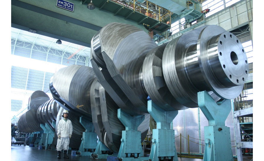
Crankshaft for marine diesel engines have been discussed in this article. They are of many types and is used as per the need for a particular type of requirement. After piston takes away the combustion forces developed during ignition, it transmits forces to crankshaft, and gives it a circular cyclic motion.
The shaft and the form of the crankshaft itself looks very difficult to make and also bigger engines require more bigger shafts, which are difficult to be made. From single piece forged shaft to assembled shafts, all are used as per the need. Mostly the small engines like cars etc, have a shaft which is made from single piece only. And the process is forging. In this article we will discuss types of crankshaft, stresses, forces and deflection involved with them.
Types of Crankshaft
Following types of shafts are there:
- Forged Shafts
- Fully Built Shafts
- Semi Built Shafts
- Welded Shafts
- Forged Shafts
As name suggest, they are made by using the technique of forging. In forging a single piece of metal is forged to form the a single piece shaft. No joining or welding of parts is done.
In this white hot metal is placed in a lower die, while the upper half die is on a vertical moving hydraulic machine. Top die is repeatedly dropped on the bottom one from greater height. This slowly leads to make a desired form for the shaft. It is similar to hammering a soft metal into a hole and the soft metal will take the shape of that metal.
But bigger shaft like for large two stroke engines is difficult to make considering the weight and the size. So the shafts for medium speed engines like generators are made by this technique. And such shafts have uniform grain size. Sometimes holes are drilled through for lubrication.
Full Built Shaft
As name suggests, these kind of shafts are built parts by parts. The diagram shown below shows the parts which are joined to form a shaft.

Mostly web pieces are made by forging and then pins are shrink fitted to make a complete shaft. Pin usually have more diameter than the hole. So either hole can be heater to put pin or the pin can be cooled down to get a perfect fit.
This process of making shafts is easy in the sense that small parts are joined to make a bigger shaft. So handling pieces become easy. Fully built shafts are more heavy as they made of extra metal to bear the shrink forces. This leads to making of shaft very heavy and thus difficult to make. They are not used anymore.
Semi Built Shaft
As name suggest, they are not assembled from many parts as compared to the fully built shaft. In this the fully built crank webs are forged and they are shrunk fit to the bearing general. So the crankpin material is same as the crankweb and they are machined further to give smooth surface finish. Mostly nowadays the shaft for the large Diesel engines used for the ships main engine are made from this kind of process.

By this process we get a continuous grain structure all over the crank web and avoid heat damage to the holes of the crank web while putting journal into it, we usually cool down the journal with liquid nitrogen for putting it to the crank webs. Also, all the sharp corners on the web are cold rolled to reduces the stress raisers and almost eliminate them. For the purpose of lubrication, internal passage are made in the web.
Welded Shaft
In this kind of method or types of shaft making, all parts are assembled by the process of welding. So half web is welded to the other half by welding. Same is used to join journal to the crank webs.

Although only few shaft were made with this process but they were very good in terms of strength lasted very long interval as compared to the other types of shafts. But cost to make them was so much that they were finally being stopped from being made.
Crankshaft Stresses
Following are the kind of stresses that acts on a shaft and they are as mentioned below:
- Torsional
- Bending
- Axial
- Shear Forces
Torsional stresses occur due to the twisting forces developed in the shaft when it rotates. Actually it twist in one cycle and then untwist itself on the other one. Shaft should be able to take such reversal of cyclic loads and not fail under such conditions. Generally we only see the average speed of the engine, but in actual conditions it may be less or more, depending on the different units firing at that time.
So sometimes it retard or accelerate depending on the firing of each unit.
Bending stress are developed due to the firing and compression forces developing on each unit and also when the load changes. So a unit which is not firing will have lesser load on it’s crank while the one which will fire going to impose more load.
Also if the bearing clearances are out of limits, there will be more bending on the shaft.
AXIAL stresses come on the shaft from the propeller side, also the hogging and sagging of the shaft. Axial vibration damper is fitted to dampen such stresses.
Shear stresses are developed when the crankpin is in stress due to compressive forces developed by the combustion gases. And a moment is developed around the journal bearings, causing a shear force.
Deflection for the Shaft
Taking deflections for a shaft is quite important activity onboard. Deflection reading is a sign of wear and tear of the main bearing. Also it indicates any sagging of the transverse bearing carrier.


Very good information to the beginners of automobile engineering
I appreciate your work , thanks for all the informative blog posts.
I’ve been visiting your blog for a while now and I always find a gem in your new posts. Thanks for sharing.