Introduction to Screw Pump
Screw pump has a structure same like a screw. I mean the whole construction of the spindle is like a archimedes screw and this spindle is responsible for the pumping action of the pump. It has been observed over the years that this pump requires least maintenances and therefore, is a potential device for increasing the pressure. As other pumps, screw pump too takes the mechanical or you can say the rotational energy from external means like a motor or any type of arrangements which provides the rotary motion. Sulzer and kirlosker pumps are very famous. So let’s discuss about this pump little more detail.
Construction of the Screw pump
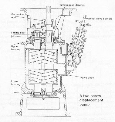
Construction of screw pump is coherent and very straight forward in its making. See the diagram for construction details. Screw pump is having three screw spindles, one of which is driver and other two are driven. There is a fine clearance between these screws and this fine clearance is responsible for the pumping action of the fluid. Drive to the main screw is given through the motor which is coupled to this by proper coupling.
Pumps have a casing which has a proper inlet and outlet. Inlet is always preferred at the bottom and the outlet is preferred at the upper part of the pump. This is all we have in the construction of this pump. One more thing which I forget to tell is that this pump is having a relief valve fitted at the end of the outlet.
Working of the Screw Pump
Screw pump is having the simplest working on the entire pumps. Let’s start with fluid coming at inlet at the bottom most part of this pump. Now since driver screw is rotating and other two drive screws are also rotating but in different directions, they tend to build up the suction pressure at the bottom part. This suction pressure makes the fluid to move upward. Fluid passes through the small clearance between these screws and also the centrifugal force is experienced by this fluid. Both of these factors contribute towards providing the force which in turn results in the development of pressure in the fluid.
This pumped oil get out of the pump, with pressure but before going out of the pump, it has to pass through the monitoring of the relief valve. A relief valve is a mechanical device or mounting which guarantees that fluid is given by the pump in the limited pressure range. If the pressure of the fluid increases, then automatic relief valve will direct the excess pressure oil into the inlet side or we can say the suction side.
Problem and maintenances required on Screw pumps
Generally we have very less problems associated with this
pump but yes some problems occur. To make things simpler, let’s discuss the problems which may occur on this pump.
- The clearances between the screws increases, which results
in a decrease in pressure.
- Bearings may wear out.
- The relief valve does not function properly.
So these were some of the problems which we face in screw pumps.Let’s discuss the maintenances which are done with this pump.
- Checking the clearance between the screws and rectifying it.
- Bearings lubrication and oiling.
- Checking and testing the relief valve.
Material used in making different parts of the screw pump
Followings parts are made with the metals described below:
Casing: Generally made of cast iron.
Screw shafts: Made of high grade carbon steel.
Bearings: High speed steels.
Applications of Screw pump
Normal the screw is used for pumping the high viscous fluids. They are also used for draining out the tanks having high vapor pressure liquids. They are used to take the water from the stern tube area, if there leakage there. So these are some of the uses of the screw pump.


How to measure the clearance between the screws and what are the limits of clearances to be maintained
We can use feeler gauges and clearances can be between .20mm to .50mm, i guess
I want a pump for pumping the Diethanol amine which has a viscosity of 351 Cp.Please suggest the type of screw pump which i can use and i need to have the head of 30 mt.
Working principle of screw and gear pump?TIA