Introduction to Gear Pump
Gear pump is among the important pumps, which are used on board ship. They are basically having gears, and these gears are responsible for the providing pressure energy to the fluid flowing through it. They mainly find their application in the lubrication oil transfer and hence are fitted with the main engine lubrication system. So, let’s study about this pump in little more details.
Construction of Gear pump
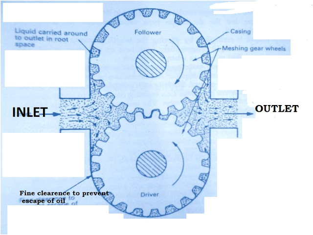
The construction of the gear pump is pretty simple and lucid to understand. First see the drawing given below and see the parts listed there.
As you can see that, gear pump consists of the two gears, one is the driver and another is the drive-in. The driver gets the drive from external means like through main engine or electric motor. These two gears are important and only moving parts in this pump. You can say that both of them are must and essential part of this pump.
We have separate inlet and outlet of this pump. But, nobody can tell which one is the inlet or outlet; it is just a matter of flow and yes, the rotation of the driven gear. One thing to be noted here, which is, for the safety of the pump we have a relief valve fitted at the end of the outlet. If the pressure goes far then the set pressure, the relief valve will direct the flow of the liquid back to the inlet and hence we will get a controlled pressure at the outlet.
The casing of the pump is as important as the gear. I mean because of the close clearance between the casing and the teeth of the gears, pressure is developed and we get the pressurized fluid at the end. This fine clearance is the main object of concern in this pump. There are several gear pump pdf books available in market. Centrifugal action of the gears helps liquid to gain pressure.
Working of the gear pump
Gear pump is straight forward and simple in their working. The working of the gear pump starts from receiving of fluid at the inlet. When the fluid moves forward due to the vacuum created behind the teeth of the two gears, it starts getting trapped into the teeth of the gears.
Now, this trapped fluid is carried away from the teeth across whole casing. In simple words we can say that, the trapped liquid passes through the region of fine clearance between ‘the casing and the teeth’. Since there is no space to go anywhere, trapped liquid gets compressed (Not in real but just gets lots of force over’ it). When the outlet sides come, this pressurized fluid rush to the outlet of the pump. Relief valve checks the pressure of this coming fluid and acts accordingly.
Problems and maintenances in the Gear pump
Each machinery having moving parts will tend to get wear and tear and thus requires maintenances too. For making things simple, I have given this information in points.
Problems in gear pumps
Loss of pressure
Teeth wear and tear
Maintenances in Gear pumps
- Checking the clearance between the casing and the gear teeth and rectifying it.
- Checking meshing clearance between the teeth and rectifying it.
- Checking the spring of the relief valve for proper action.
So, these are some of the problems and maintenances required for the gear pump.
Material used in making parts of the gear pump
Following materials are used in making different parts of the gear pump.
Shaft- Made of forged naturally steel.
Rotors- they are also made of forged nitro alloy steel.
Casing- Closed grained gray cast iron.
Uses of Gear pump
Uses of gear pump are specific and limited on the ship. They mainly find their application in the engine and gearbox lubrication in slow speed engines. They also find their applications in the fuel and oil transfer, boiler combustion systems etc.
Image courtesy: Marine auxiliary machinery by HD McGeorge.
